One Control Room for a Solar Plant’s Power and Data
A solar plant ran inverters, meters and relays on mixed protocols. Nexora designed the integration that connects them to a Power Plant Controller and SCADA, so operators monitor and dispatch from one place.

One Control Room for a Solar Plant’s Power and Data
Results
The Challenge
The plant had inverters, a substation, meters, a weather station and protection relays, and each spoke its own protocol with its own register layout. Operators could not see the whole plant, and the grid operator still expected controlled active and reactive power at the connection point. The hard part was never the SCADA screen. It was protocol integration, data mapping and keeping control signals correct across mismatched devices.
- Mixed standards: Modbus TCP/RTU, IEC 104, OPC UA and vendor-specific protocols
- Different scale factors, status codes and alarm codes per manufacturer
- Control commands that must never write a wrong register
- Automatic recovery when a group of inverters drops and returns

What We Designed
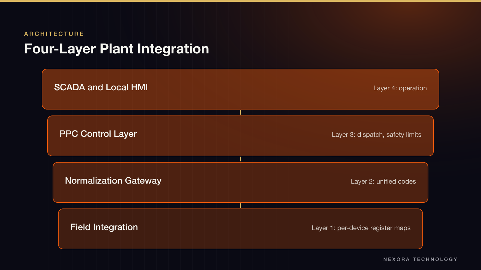
We split the integration into four layers so each problem has one owner. Field integration reads each device through its own register map. A normalization layer turns raw registers into engineering values, with scaling, units, timestamps and data-quality checks for timeouts and stale readings. The PPC layer runs power control logic, and SCADA gives operators the monitoring and command surface.
- Layer 1: field device integration with per-device register maps
- Layer 2: normalization and protocol gateway with unified alarm and status codes
- Layer 3: PPC control layer for dispatch and safety limits
- Layer 4: SCADA and local HMI for operation
How It Works
The PPC receives a setpoint from SCADA or the dispatch center and distributes it across inverter groups based on their real state. If dispatch calls for 40 MW and one group is offline, the PPC reallocates the setpoint to the inverters still running while holding each device within its technical limits. Commands pass logic and threshold checks before they reach a device.
Key Design Decisions
Every device gets its own tag map, so adding a string inverter or meter later means adding a map, not reworking the plant. Data-quality flags travel with each value, which lets alarms distinguish a real fault from a lost connection. Historical data and an event log are first-class, so engineers can trace a fault after the fact instead of reconstructing it from memory.
- Active power, reactive power, power factor, voltage and ramp-rate control
- Curtailment on dispatch command
- Power limits derived from live device status
- Optional IEC 104 link to the grid dispatch center
What the Client Gets
Operating data from the whole plant lands in one SCADA system. The PPC controls plant output against setpoints from operations or dispatch. Alarms and real-time status shorten the time to spot a fault and cut manual work for operating engineers. The same data can then feed reports, trend analysis and later analytics such as predictive maintenance.
What Nexora Covers
Nexora can take an integration like this from architecture analysis through delivery and support: reading vendor protocol documents, building the gateway and alarm logic, FAT and SAT testing, a trial run at the plant, and handover with operating guidance. Our team combines software, electrical and automation engineering, which is what this kind of integration needs.
Got a similar project?
Tell us about it. First consultation is free.